Generating Dynamic Woodworking Plans
I'm applying 15 years of software experience to generate dynamic, custom woodworking plans — picking up an idea I first had as a teenager with a ramp website.
Contents 4 sections
Don't get me wrong. I love the unlimited freedom and creativity that being a software developer provides, but it was never my first choice. I wanted to be a builder.
Reviving an old desire
Ever since I was a kid, I loved sharing my ideas and learnings for others to benefit. I grew up riding BMX bikes and skateboards, and building ramps for myself and my friends to ride.
My dad ran an internet business, so he nudged me into creating a website just
for fun. First it was just a personal site at <my-name>.com, but eventually I
decided I wanted to share ramp plans — and learn how to make dynamic websites
for this new(ish) thing called the internet.
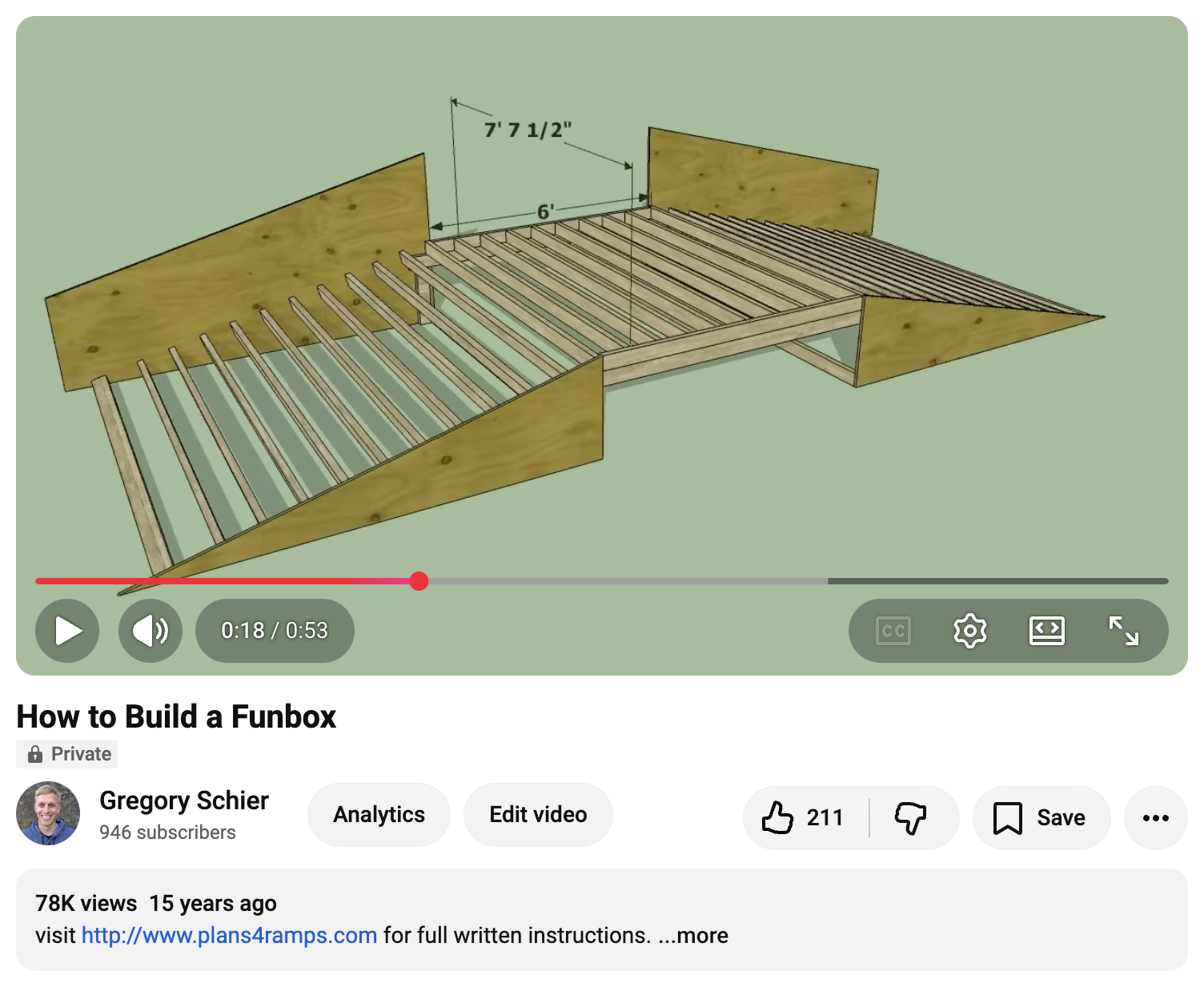
I would create 3D models of ramps and use them to generate the images, cut lists, and videos that went into easy-to-follow build plans.
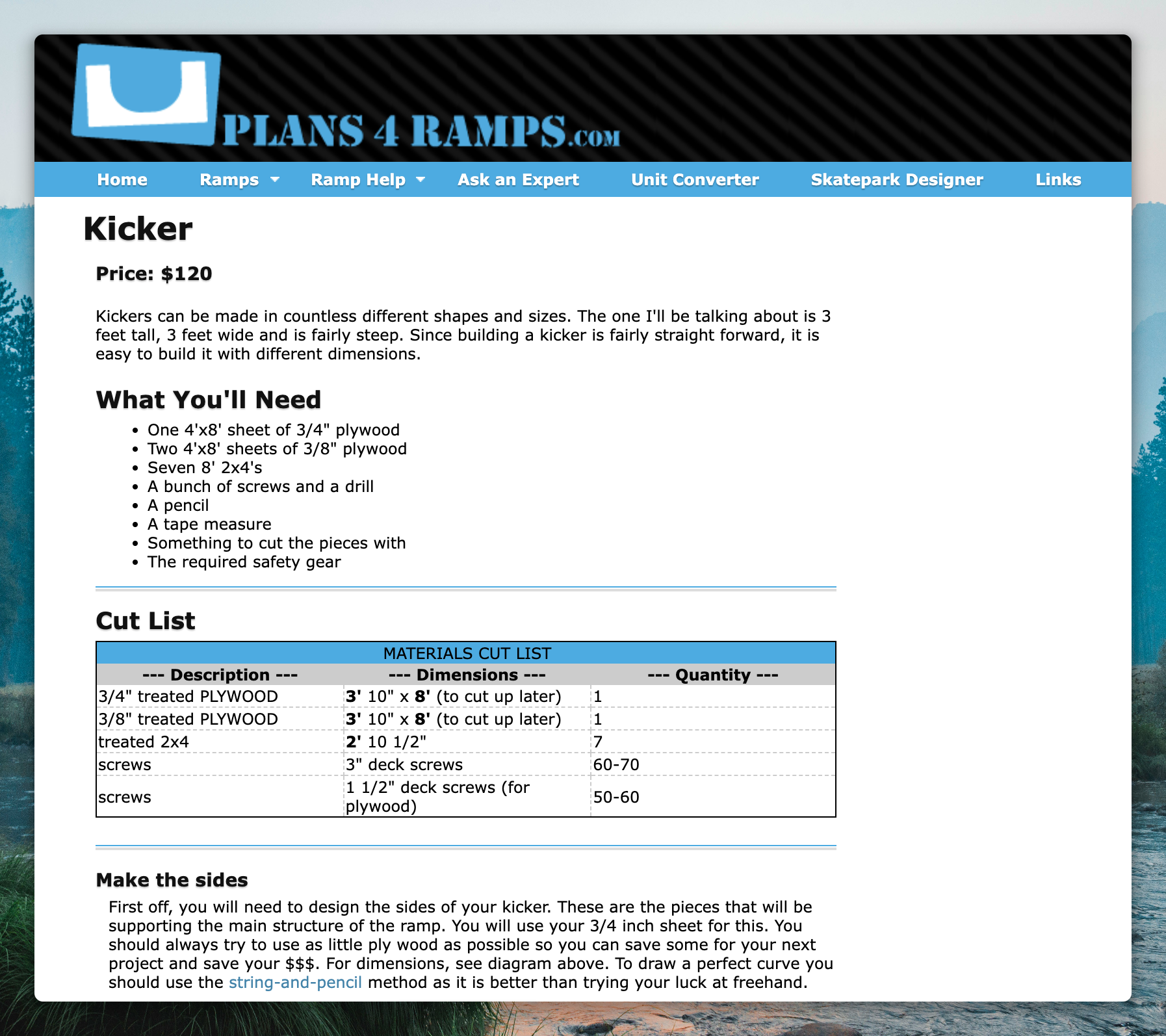
Introducing Build w/ Greg
This site takes the original plans4ramps.com idea to the next level. I got into woodworking around 2020, after finally moving into a house with enough space — and I've been dissatisfied with how woodworking plans are presented ever since:
- Plans are static, locked to the exact project shown
- Modifying a plan for your space means redoing the math yourself
- Commissioning custom plans is expensive — if you can find someone at all
So every project on this site is a small program. Not a drawing of a shelf — a build-step program that generates the shelf, the cut list, and the assembly steps for whatever dimensions you punch in. The figures in these posts aren't screenshots I exported once; they're views into that program, rendered live in your browser. I've started calling them 4D figures — the fourth dimension is the build itself, and you can scrub through it.
One engine, three surfaces
The same code renders three things: the interactive builder, these embedded figures, and the static images social media crawlers see. The server keeps a headless browser warm with the CAD kernel booted, so a poster is the actual engine output — if I change a joint, every image on the site regenerates on the next deploy.
Back to where it started
It only feels right that the first plan in this new system is the one that started everything: the kicker ramp. Same ramp I built as a teenager — except this one is a build-step program like everything else here.
The curve comes from a radius cut: anchor a string at the center point, swing a pencil arc across the panel, and cut to the line with a jigsaw — the same way I did it in the driveway twenty years ago. The build steps animate it exactly that way:
Set a different height, radius, or width and everything downstream regenerates — the side panels, the cut list, and the 2x4 members, which re-solve their own spacing along the new curve:
And because a figure is the live engine — not a screenshot — it can show you things a drawing can't. It can pull the build apart:
Or x-ray it, ghosting everything but the frame that hides under the riding surface:
The kicker lives in the gallery with everything else, and it opens in the builder — go stretch it and watch the cut list keep up.